|
on other languages Русский I started writing this article a few years ago and never could gather enough spirit to finish it. Finally, a compromise was found: I decided to publish the first "theoretical" part, and then, as soon as ready, the second "practical" part. In the second part will be demonstrated on multiple examples the majority of the cases described in the first part, reviewed styli of different manufacturers, and given tips for reshaping styli to certain sizes at home.
Review of 78-RPM styli
Part 1
Reproduction of shellac records, especially from the early period is a challenging technical task. Here, the most important role plays needles’ size and shape. Among collectors there is an opinion that a good needle may be used as one-serves-all. Unfortunately, it is far from the truth, especially when applied to the early (acoustic) period because that time there weren’t standardized major parameters of the groove such as depth, width, angle and radius at the bottom.
Besides, one has to take into account that many records survived in worn condition. There might be scratches; the groove bottom might be covered with dirt and derbies of shellac and steel needles. It’s not a rare case of some manufacturing defects, such as insufficient plunging of the stamper or printing by worn stampers.
In this work the Author tried to illustrate the Influence of size and shape of the stylus on reproduction quality on multiple typical examples.
Typical characteristics of records grooves
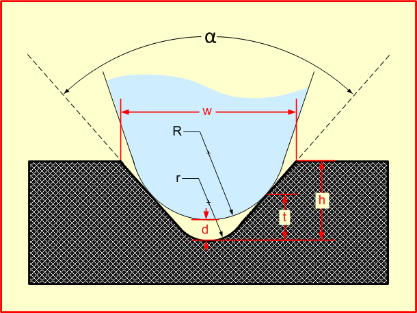
On the pic.1 shown cross-sectional view of a typical record groove and needle tip.
|
|
Pic. 1
|
|
Comparative table of typical sizes
| Parameter |
Letter |
Range 1,2 |
USSR, 1939 1 |
Typical
international
size, 1934 2 |
| Groove depth |
h |
45 µ – 90 µ |
63 µ / 74 µ |
74 µ
(2,9 mil) |
| Groove width |
w |
120 µ – 200 µ |
160 µ /180 µ |
166 µ
(6,54 mil) |
| Groove angel |
α |
70° – 110° |
85° |
86,5° |
| Groove radius at the bottom |
r |
20 µ – 63 µ |
50 µ |
38,1 µ
(1,5 mil) |
| Needle radius3 |
R |
30 µ – 76,2 µ
(1,2 mil - 3,0 mil) |
30 µ – 60 µ
(1,2 mil - 2,4 mil)
(metal point) |
61 µ (2,7 mil) (metal point)
76,2 µ (3,0 mil) (sapphire) |
| Max needle radius4 |
Rmax |
– |
78,3 µ / 91,97 µ
(3, 08 mil / 3,62 mil) |
95,57 µ
(3,76 mil) |
|
Tab. 1
1 E.I. Regirer. Phonograph Record, Moscow-Leningrad: State Scientific and technical publishing of chemical literature, 1940. In the absence of an all-Union standard for the dimensions of the groove, the book lists the dimensions accepted by the plants that are part of the Glavshirepotreb system (GSP), p. 128. The size of gramophone needles included the all-Union standard OST NCM 4213, introduced by Glavshirepotreb and approved on November 21, 1937, p.732.
2 F. Langford-Smith, Radiotron Designer's Handbook, Amagamated Wireless Valve Company Pty., Ltd., Sydney 1934, стр. 710. One can download this book from here
3 Sizes of the styli on the illustrations are given in mills that is 0.001 inch. This measurement system is used by the needles manufacturers, so it is the most convenient one for the current overview. In order to convert into micrometers (µ) one has to multiply by 25.4.
4 The radius of the needle, at which the point of contact of the needle and groove is at the highest point of the groove (i.e. on the surface of the disc)
"It's hard to say," Regirer writes, "which dimensions are optimal, since there are not enough comparative studies published. It can only be noted that a more sharp opening angle and smaller groove radius at the bottom are often considered preferable for high-quality reproduction."
And another quote from the same source: "groove profile, i.e. the shape of its cross-section, unfortunately, is not standardized on international scale and has many different dimensional options. Being different by different companies, the profile is not always consistent even within the same company."
The main factors of records wear

|
|
Pic. 2
|
|
On Pic. 2 shown the cross-sectional view of a worn phonograph record. The needle has two points of support ① on the groove walls by which it slides without touching the bottom. At these points occurs the most of the groove wear.
This example shows that the needle already dug the walls so at the points of support ① appeared recesses and the tip of the needled advanced closer to the bottom. Visually, the grooves of such records look gray. On the bottom of the groove accumulated dirt and debris ②. On the surface may appear scratches: shallow ③ and deep ones ④. In the worst cases may appear chips and cracks. From the picture we can make the following observations:
1. For noise reduction they make the surface of the records glossy, sometimes even laminated. The worn surface is not glossy anymore hence more noisy.
2. The worn groove gets wider and loose its original shape ①. It causes increased level of noise and appearance of non-linear distortion.
3. Shallow scratches ③ with their bottoms above the points of support will not be noticed by the needle during playback and will not cause clicks.
4. In order to decrease the adverse effects of the above factors, one can vary the size of the needle, so it will follow either above or below the worn area.
5. Because of wearing the tip of the needle will get lower hence decreasing the clearance d (Pic.1). This will increase the possibility that tip will touch the debris on the bottom of the groove during playback. In order to decrease this factor it is recommended thoroughly wash and dry all records and also use truncated needles. (See “Truncated needles” chapter).
6. Deep scratches ④ with their bottoms below the points of support will case laud clicks. The wider scratch and the smaller size of the needle the stronger clicks.
Impact of needle size
Playback by needles of smaller than nominal size
Playback of warn records by needle of smaller size may dramatically improve the sound quality because the needle may follow the groove below the worn area as it is shown on Pic. 3. However, there may appear some undesirable effects:
1. The tip of the needle gets even lover, so with more probability it may touch the debris on the groove bottom;

|
|
Pic. 3
|
|
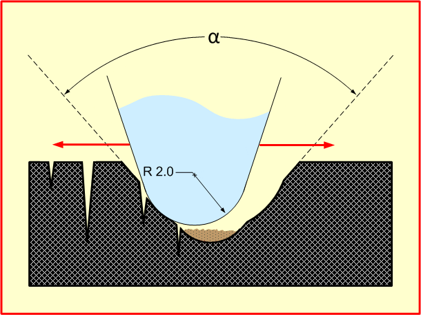
2. There is a chance that the needle won’t follow the groove below the warn area but sometimes it will be popped out of the groove into it and wander from wall to wall (Pic. 4) causing a lot of noise. For elimination of this effect one can try to increase the tracking force, fine tune the anti-skating and eliminate the record eccentricity if such exists but remember that the excess of the tracking force will increase wearing of the record and may cause touching of the bottom of the cartridge to the surface of the record.
|
|
Pic. 4
|
|
Truncated needles
For decreasing probability of touching the debris on the groove bottom by the tip of the needle they produce “truncated” needles that became very popular these days (Pic. 5).

|
|
Pic. 5
|
|
Playback by LP needles

|
|
Pic. 6
|
|
While talking about playback by smaller size needles we cannot avoid the case of using LP needles (Pic. 6). The size of needle for LP monophonic records is 25 µ (1 mil), for LP stereo records is 18 µ (0.7 mil). As it is clearly depicted on the following illustration, the tip of the needle will slide by the bottom of the groove. There is nothing good in the endeavor for the following reasons:
1. The needle tip will be “plowing” all the debris that accumulated on the bottom of the groove;
2. The area of contact of the needle and the groove is single pointed;
3. Since the radius of the needle tip is very small it will be heavily scratching over the roughness of the groove surface while a needle of bigger size would be smoothly sliding over them.
Playback by bigger than nominal size needles

|
|
Pic. 7
|
|
Playback of warn records by needle of bigger size may also dramatically improve the sound quality because the needle will follow the groove above the worn area (Pic. 7) as it is shown on the following illustration. The second positive factor is that the tip of the needle gets upper increasing the clearance between it and the groove bottom, so it may touch the debris on the groove bottom with less probability. The undesirable effects are:
1. All scratches and other defects of the surface will affect more;
2. Increased the tendency of skipping, so increasing of the tracking force, fine tune of anti-skating and get rid of the record eccentricity.
Playback by bigger than maximal size needles
Playback by a needle of a size larger than Rmax (see Tab. 1) shown on Pic. 8. In this case, the needle slides over the upper edge of the groove. Obviously, such playback leads to a deterioration in the quality of playback due to the fact that the needle will not follow accurately all bends of the groove (poor tracking). Probably the most affected will be the high frequencies, however, the nonlinear distortions will increase sharply for low frequencies too. The tendency of skipping will also increase.

|
|
Pic. 8
|
|
Manufacturing defects of records
The main records pressing defects are insufficient printing, pressing by worn stampers, poor quality of the shellac mass, records warbling and eccentricity.
Insufficient printing
|
|
Pic. 9
|
|
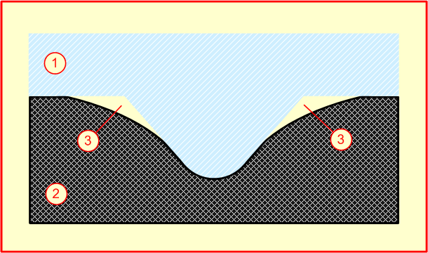
Insufficient printing (Pic. 9) is when shellac mass ② incompletely fills all the hollows of the stamper ① resulting in appearance of air sinuses ③. Insufficient printing can be caused by too sick and ropy mass (because of foul composition), insufficient heat temperature, insufficient time under press and other fouls of the technological process. For instance, the technological process of RCA Victor requires heating the mass to 310F, pressure 1800 lb. per sq. inch, and the pressing time of several seconds (the total time is about 48 seconds per record). Violating any of these parameters will case the insufficient printing.

|
|
Pic. 10
|
|
As you can see from Pic. 10, the insufficient printing resulting in wider groove with less sloppy edges, so the needle will be positioned close to the groove bottom, and also it will have the tendency of skipping forward or backward. The little sloppiness of the edges will cause distortions because of lateral sliding of the needle over the surface of the groove that will be more prominent on laud places. Unevenness of the “air sinuses” will cause additional distortions of the sound. The positive results could be achieved by usage of narrow needle, increased tracking force and tuning the antiskating.

|
|
Pic. 11
|
|
On Pic. 11 shown one more theoretical kind of insufficient printing when the stamper insufficiently plunged into the mass, but I do not know whether it is ever happens in reality.

|
|
Pic. 12
|
|
Skipping may occur during playback (Pic. 12), a small needle may help to prevent it.
Worn stampers
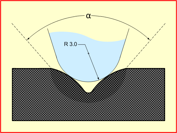
One copper stamper is good for printing about 500-600 copies; the nickel one is good for about 2000. After this number of printings start to appear the traces of worn that lowers the quality of the groove and as a result the quality of the recorded sound. How stamper gets worn? First, wipes out the metal because of friction between the mass and the surface of stamper during printing. The erosion is proportional to the pressing on each point on the surface, movement speed and the movement time. It is non-linear function: on the tip the pressure is higher, the time is longest, but the speed is close to zero, so the worn is low. A little bit off the tip and the speed dramatically increased and hence the worn. At the surface the pressure is low and the time is short, so the high speed may or may not cause the great worn. It looks like the most worn occurs on the middle part. Pic. 13 shows records printed from the stamper that was worn such way:
|
|
Pic. 13
|
|
If the metal is soft, the great role may play metal deformation. During printing it gets crumbled and smashed. As a result, the groove becomes wider and shallower as it is shown on Pic. 14:

|
|
Pic. 14
|
|
As you can see, a standard size needle just slides on the bottom of the groove with all the consequences. Playback of such record by larger size needle may improve the sound quality, as it can be seen at the Pic. 15:

|
|
Pic. 15
|
|
Impact of stylus shape
There are two kinds of styli: conical (spherical) (Pic. 16) and elliptical (Pic. 17).
C - Conical (spherical). The stylus trunk is conical and the stylus tip has shape of semi-sphere. These are the cheapest and therefore the most common styli. The most important characteristics are the radius of the sphere and the material that can be either corundum or diamond:

|
|
Pic. 16
|
|
E – Elliptical or bi-radial. The stylus tip has shape of ellipsoid that characterized by two radiuses: the big one (lateral) and the small one. The most important in lateral radius, so the small one is often omitted.
|
|

|
|
Pic. 17
|
|
Mismatch of touch points
|
|
Pic. 18
|
|
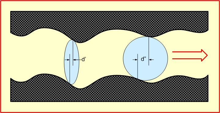
Pic. 18 demonstrates the major drawback of spherical styli: the mismatch of touching points. Because of its large size, the touching points on the outer and inner surface of the groove have a large distance (d”) along the movement of the needle. It means that for example instead of the recorded sinusoid the needle will reproduce combination of two sinusoids shifted on d” that will cause non-linear distortions. How noticeable they are? The calculations show that for 3mil needle moving on the most outer groove, for 7 kHz signal “top” of the one side will correspond to the “bottom” of another side, so they will mutually compensate each other. For other frequencies there will be modulations. The elliptical styli are pretty much free from this problem due to small distance (d’).
Pinch effect

|
|
Pic. 19
|
|
Another drawback of spherical styli is “pinch effect”. It can be well understood from the followong illustration: when stylus is passing the windy track, due to it large size it cannot squeeze itself between two sides and has to move up. This movement can cause distortions.
Roughness smoothing

|
|
Pic. 20
|
|
Along with drawbacks, the spherical styli enjoys one advantage: when playing very warn records it smoothing roughness of the groove surfaces by sliding over them while elliptical styli will nudge them (Pic. 20).
Yuri Bernikov
To be continued...
|